ST 131, ST 131N «PIRANHA II»


The difference between “ST131 PIRANHA II” and ST131N is the presence of ST131N an additional option: " NON-LINEAR JUNCTION DETECTOR in wired lines".
Externally, the differences consist in that ST131N has an additional connector on the front panel of the main unit and the fourth wire in the wire line adapter ST131AWL.N.
The main types of the Bugging devices, for detection of which ST131 is intended, include the following:
The Bugging devices with transfer of information by radio channel. Such devices include first of all:
- Radio microphones including devices with storage and subsequent transfer of information (burst transmitter) and Frequency Hopping Spread Spectrum (FHSS);
- Radio stethoscopes.
- Wireless cameras.
- Mobile phones and modems of the CDMA, GSM, 3G, DECT standards used without authorization.
- Devices using digital channels of data transmission of the 4G, WLAN and BLUETOOTH standards.
- GPS tracker
The Hardware wiretap that uses telephone, coaxial, security and fire alarm lines for information transfer in an audio and RF fraequency ranges
Carrier Current Bug
The Bugs that are characterized by transmission of information in an infrared and visible frequency ranges
The Bugs that are characterized by transmission of information in an ultrasonic frequency ranges
Detection of electronic devices (digital voice recorders, mobile phones and smartphones in standby mode, and so on) based on the their spurious electromagnetic radiation.
Construction of ST131 / ST131N envisages two basic modes of operation:
- Portable, using the capabilities of the main unit and attachments
- Stationary, using the original software "ST131Analyzer.pro".

|

|
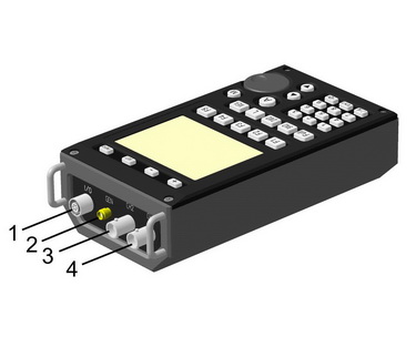
MAIN UNIT
|
|
1 |
Control socket |
|
2 |
Output of test signal generation (only for ST131.N) |
|
|
3 |
Socket for connection of transducers operating in ACOUSTOELECTRIC channel and Magnetic Field Probe | |
|
4 |
Socket for connection of wire line adapter (WIRE LINE channel) and HF antenna (RADIO channel 0.01-30MHz) |
|
|
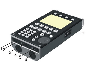
1 |
Line Out |
|
2 |
"3.5" socket for connection of headphones | |
|
3 |
Volume control | |
|
4 |
Battery compartment covers. |
|
|
5 |
Power ON/OFF | |
|
6 |
Power supply socket | |
|
7 |
USB socket |
|
|
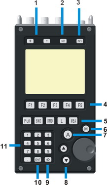
1 |
"+" and "-" increase/decrease of display brightness level and switching between the bands |
|
2 |
"SET" entry in main MENU | |
|
3 |
"INFO" - viewing the current settings of the device | |
|
4 |
CONTEXT BUTTONS Purpose of the context buttons F1 – F5 is to indicate in the lower line of the display such information that depends on the selected channel and operating mode in this channel. |
|
|
5 |
FUNCTIONAL BUTTONS
"Full"- switching on the mode FULL RANGE "DMD" - switching on the mode DEMODULATION
"L" - -switching on the sub-mode SCALE |
|
|
6 |
"M" - switching on the sub-mode MEMORY | |
|
7 |
"A" - switching on the sub-mode AUTOMATIC ANALYSIS | |
|
8 |
"><" - manual selection of noise level relative to zero value and choosing items in the MENU | |
|
9 |
">0<" - automatic calculation of noise level relative to zero value | |
|
10 |
"ENT" - entering function (pressing VALCODER also equal to press ENT in most cases) | |
|
11 |
"0-9, ." - digital keyboard |
SOFTWARE
SPECIAL SOFTWARE "ST131 ANALYZER PRO" EXTENDS CAPACITIES OF the ST131 FOR ANALYSIS AND PROCESSING OF SIGNALS.
|
This software is implemented the following functions:
|
|
|
|
|
|
|
|
|
|


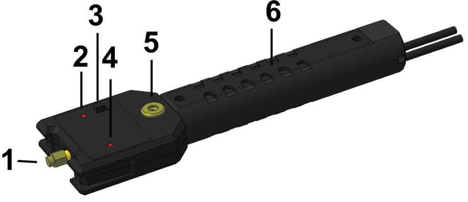
UHF CONVERTER ST131.UHF
UHF converter is a downconverter of 30 – 4400 MHz frequency range into the frequency range of the WIRE LINE channel.
|
|
1 |
SMA socket |
|
2 |
Switching-on and battery discharge LED |
|
|
3 |
Power switch ON/OFF |
|
|
4 |
Data exchange LED |
|
|
5 |
Thread opening 1/4” |
|
|
6 |
Battery compartment cover |
WIRE LINE ADAPTER ST131.AWL/ST131.AWLN
ST131AWL has been constructively combined:
- the reducing voltage converter transformer which is designed to operate in the frequency range of 0.01 - 30 MHz;
- high gain differential amplifier which is designed to use in the acoustic frequency range (0.3 - 15 KHz);
- the switching unit which is controlled directly from the main unit and provides connection to the contact pairs of the RJ-45. Connection is possible for the most common combinations of pairs ("4-5", "3-6", "1-2") as well as user-defined selection.
- the amplifier of the test signal generator (Only for ST131.AWLN);
Connecting to the line occurs with:
- connector RJ-45 (3) which provides connection to ETHERNET or telephone line as well as pass-through connection;
- connectors for connecting test leads (1) that provide connection to other types of wire lines;
|
|
1 |
Bananas |
|
2 |
Ground connector |
|
|
3 |
RJ-45 socket |
|
|
4 |
Indicators of voltage in Line (LINE) | |
|
5 |
Indicator of overload of signals (OVERLOAD) | |
|
6 |
Indicator of power supply and link with the main unit (PWR/LINK) |

RADIO WIRE LINE ADAPTER ST131.RAWL

ST131.RAWL is intended to operate the WIRE LINE channel in the frequency range of 30 - 3000 MHz.
ST131.RAWL has been installed components that protects against failure of the input circuits of the UHF converter.
ST131.RAWL connects to a single-type connector «SMA» of the UHF converter ST131.UHF. Input connector type "F" is designed for direct connection to the coaxial lines. For connecting t to the lines with BNC type connector use an adapter «BNC-F».
UHF ANTENNA (ST131.UHF.A)
ST131.UHF.A is a broadband passive antenna
|
|
1 |
SMA socket
|
2 |
Antenna
ADDITIONAL EQUIPMENT
SHF DETECTOR "ST131.SHF"
TESTING DEVICE "ST131.TEST"
INFRARED PROBE ST131.IR
BIASING MODULE ST131.0V
DETECTING CHANNELS
CHANNEL "RADIO"
WIRE LINE CHANNEL
This channel provides the reception and the subsequent processing of the signals which are transmitted by wires for different purposes (power, telephone, coaxial, computer networks, security and fire alarm systems, etc.). The allowed voltage in the lines (DC or AC) is up to 250 V.
To work in the ranges of 0.3 - 15 KHz and 0.01 - 30 MHz is used the wire lines adapter "ST131.AWL".
To work in the range of 30 - 1000 MHz is used the adapter "ST131.RAWL" with the UHF converter.
OPTICAL CHANNEL
Receiving and processing of theemission in the optical frequency range is provided in this channel.
Infrared detector ST131.IF is intended for operation in this channel.
ACOUSTIC-ELECTRIC CHANNEL
Receiving, amplifying and analyzing of signals within the frequency range of 10 Hz – 125 kHz is provided in this channel.
Application of one or other types of acoustic transducers depends on the tasks taking into account parameters of this channel.
Ultrasonic signal is converted into audio frequency signal by means of digital heterodyning.
For the detection of side electromagnetic emission generated by devices such as digital voice recorder, cell phone, smart phone, etc. intended a magnetic field sensor "ST131.MF".
| Work in entire frequency range |

|
|
Detailed analysis of the signals in the selected band Decrease of the swath increases signal/noise ratio in inverse proportion to the band in addition to increase horizontal resolution |

|
|
Аudio control of the demodulated signal. |

|
|
Multi-segment scale level of signal Sсфду is the most required option in case of localization the STM. |

|
|
Automatic detection of signals exseeds predetermined threshold with creation of database |

|
|
Instant and detailed patterns Detailed pattern automaticaly adapted for any range |

|
|
Analysis of signals in the frequency and time domain Absolute and relative measurements using cursor lines |

|
|
Creating a list of signals in automatic and manual mode Transfer data to PC |

|
|
Special indicator levels of signals cellurar and wireless data transmission Level meter of signal of base station |

|
| Automatic and manual analysis of pairs of ETHERNET cable |

|
|
NON-LINEAR JUNCTION DETECTOR OPTION (only for ST131N) |

|
|
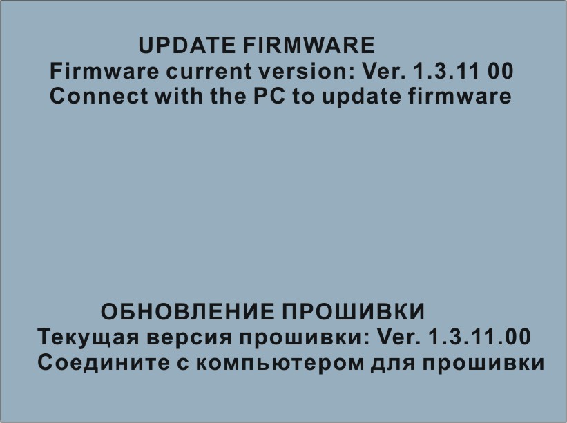
FIRMWARE UPDATE Updates take place automatically when you select the latest version of the software at manufacturer's website and start the upgrade. |
|
| SPECIFICATIONS | |
| DIGITAL SIGNAL PROCESSING MODULE | |
| Simultaneous processing frequency range, MHz |
0.01 - 30
|
| Resolution ADC, bit |
10, 14, 16
|
| Number of FFT points |
32768 (PC mode), 512 (main unit)
|
| Bandwidth, MHz |
0.0005 - 10 I`Hz
|
| Demodulation types |
AM, FM, SSB, TV (AV)
|
|
"RADIO" CHANNEL |
|
| Frequency range1, MHz |
0.01-30
|
|
Displayed noise level Within the whole bandwidth, dBm Within DDC bandwidth 1 kHz, dBm |
-110 -150 |
| Value of the possible bandwidth, MHz | 10, 5, 2, 1, 0.5, 0.2, 0.1, 0.05, 0.02, 0.01, 0.005, 0.002, 0.001, 0.0005 |
| Frequency range2, MHz |
30 - 4400
|
|
Displayed noise level Within the whole bandwidth, dBm Within DDC bandwidth 1 kHz, dBm |
-110 (PC mode), -90 (main unit)
- 130 |
| Input signal maximal level, dBm |
5
|
| Sweep speed, GHz/sec, max |
10
|
| Value of the possible bandwidth, MHz | 2048, 1024, 512, 200, 100, 50, 20, 10, 5, 2, 1, 0.5, 0.2, 0.1, 0.05, 0.02, 0.01, 0.005, 0.002, 0.001, 0.0005 |
| Identified data transfer standards | CDMA, GSM, 3G,4G, WLAN, BLUETOOTH, DECT |
| Frequency range3, MHz |
4000-18000
|
|
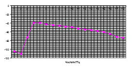
Graph of dependence the demodulated output signal at a frequency of 10 kHz from the frequency of the microwave signal incident on the antenna of the electromagnetic wave with a constant (frequency-independent) the electric field intensity 0.7 V/m. |
|
| Threshold sensitivity, W/cm2 | -65 |
| Antenna beamwidth, degrees |
60-90
|
| "WIRE LINE" CHANNEL | |
| Frequency range 1, MHz |
0.01-30
|
| Displayed noise level in full range |
- 90 (120 for PC mode) |
|
at 1 kHz band for Main Unit, dBm, not worse |
-125 |
| Input signal maximal level, dBm | 20 |
| Maximal permitted input voltage, V | 380 |
| Value of bandwidth IF, kHz |
6800, 2500, 630, 150, 75, 40, 10, 5, 1 e` 0.5
|
| Gain input amplifier |
-5, 1, 7, 13, 19, 25, 31, A`KG
|
| Frequency range 2, KHz | 0.3 - 15 |
| Displayed noise level in full range, dBm, not worse |
-115 (140 for PC mode) |
| Input signal maximal level, dBm | 20 |
| Gain input amplifier |
14, 26, 38, 44, 50, 56, AKG |
| Common-mode interference attenuation factor, dB | 60 |
| Maximal permitted input voltage, V | 250 |
| Frequency range 3, MHz | 30-3000 |
|
"OPTICAL"CHANNEL
|
|
| Dynamic range, dB | 60 |
| Frequency range, MHz | 0.01-30 |
|
INFRARED PROBE ST131 |
|
|
Spectral range, nm |
770-1600 |
| Angle of sight, degrees | 30 |
| Wire length | 1.5 |
|
"ACOUSTOELECTRIC" CHANNEL
|
|
| Frequency range, KHz |
0.01-125
|
|
Displayed noise level in full range, dBm, not worse |
-100 (148 for PC)
|
|
at 1 kHz band for Main Unit, dBm, not worse |
-120 |
| Input signal maximal level, dBm | -5 |
| Gain input amplifier |
6, 14,20, 26, 34 e` 40 |
|
MAGNETIC FIELD ST 131 |
|
| Frequency range, Hz | 30 – 30000 |
| Transformation ratio (1000Hz), B*m/A | 1.00±0.01 |
| Threshold sensitivity, A/m*Hz1/2 ,less than | 2*10-6 |
| NON -LINEAR JUNCTION DETECTOR | |
| Frequency of test signal, kHz | 150-220 |
|
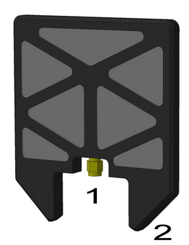
MAIN UNIT
|
|
| Dimensions, mm |
190x97x50
|
| Indication |
3.5” 240x320, TFT 262144 colors
|
| Interface | USB 2.0, 200 Mbit/s |
| Power supply |
6 AA batteries (rechargeable batteries)
|
| DELIVERY SET | ||
| Main unit |
1
|
|
| UHF converter (ST131.UHF) |
1
|
|
| Broadband UHF antenna (ST131.UHF.A) |
1
|
|
| Wire line adapter (ST131.AWL) | 1 |
|
| RF wire line adapter (ST131.RAWL) | 1 | |
| Probes set + alligator clips |
1
|
|
| 220V clips + "GROUND" wire | 1 | |
| «F-BNC» adapter | 1 | |
| Main unit supporting block |
1
|
|
| Main unit shoulder holder |
1
|
|
| Headphones |
1
|
|
| Tripod |
1
|
|
| Power supply unit |
2
|
|
| USB cable | 1 | |
| AA batteries |
8
|
|
| USB Flash with software |
1
|
|
| Hex-nut wrench | 1 | |
| User manual |
1
|
|
|
Supplementary set
|
||
| SHF Detector ST131.SHF | ||
| IR probe ST131.IR | ||
| Magnetic field probe ST131.MF | ||
| Testing devie ST131.TEST | ||
| Biasing module ST131.OV | ||