ST131.S


The main types of the STM, for detection of which ST131.S is intended, are:
The STM with information transfer in the infrared frequency range and ultrasonic frequency range.
Differences from he previous devices:
- The frequency range of the first channel "Radio" extended to 6 GHz
- The UHF converter is located in the main unit.
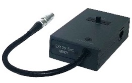
- The bias voltage supply module is located in the wire line adapter.
- Powered by Li pol type 16650 batteries.
- Keyboard backlight
Construction of ST131.S envisages two basic modes of operation:
- Portable, using the capabilities of the main unit and attachments
- Stationary, using the original software "ST131Analyzer.pro".
Components
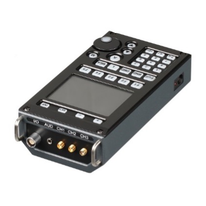
Main unitIs the basic element of the devices
|
 |
Software
|
 |
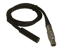
Wire lines adapter «ST131.S.AWL»ST131.S.AWL is a monoblock in which structurally united:
|
 |
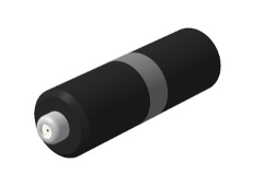
RF wire line adapter «ST131.S.RAWL».ST131.S.RAWL is a single monoblock with integrated circuit protection against high voltage up to 250V. |
 |
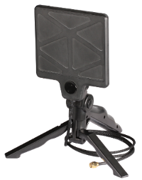
UHF antenna "ST131.S.UHF.A"
|
ST131.S.UHF.A is a passive broadband antenna. |
|
Testing device "ST131.S.TEST"
The "ST131.S.TEST" is intended to control operability of device ST131.S by testing all detection channels in the main unit as well as rest equipment (sensors, antennas, adapters, converters). | 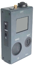 |
The "ST131.S.TEST" has six control signal sources corresponding to the ST131.S detection channels as well as non-linear element to check the non-linear junction detector. |
1.3.7 Magnetic field sensor ST131.S.MF.ST131.S.MF consists of a ferrite antenna and pre-amplifier.ST131.S.MF operates in two modes: |
 |
«MAGNETOMETER"- directly as a magnetic field intensity sensor |
|
"GRADIOMETER" - In this mode an influence of remote strong sources of magnetic field is reduced significantly as well as influence of other disturbing impacts (acoustic, vibro-acoustic, etc). |
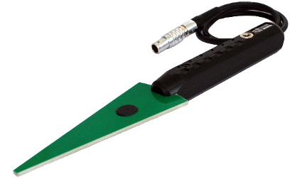
SHF antenna-detector "ST131.S.SHF"ST131.S.SHF consists of the structurally integrated log-periodic antenna and SHF detector-amplifier. |
 |
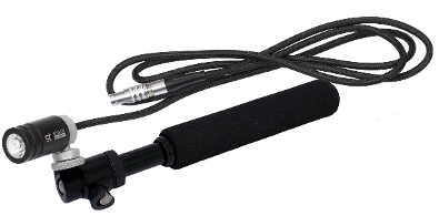
Infrared sensor "ST131.S.IR"
This sensor structurally consists of receiving photodiode and pre-amplifier. The front side of sensor has the screw-thread hole 1/4" used for connection of the special monopod or tripod. |
 |
Acoustic sensor "ST131.S.A" Designed to receive acoustic signals in the sound and ultrasonic frequency range. Microphone and amplifier are structurally combined in this sensor |
|
DETECTING CHANNELS
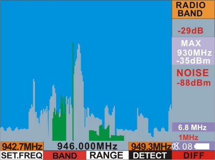
CHANNEL"RADIO"
This channel provides the reception and the subsequent processing of radio signals in the frequency range 0.01 - 18000 MHz.
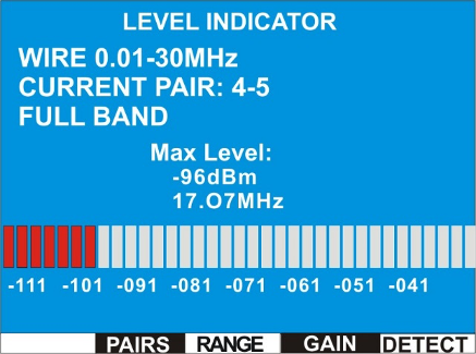
WIRE LINE CHANNEL
This channel provides the reception and the subsequent processing of the signals which are transmitted by wires for different purposes (power, telephone, coaxial, computer networks, security and fire alarm systems, etc.
OPTICAL CHANNEL
Receiving and processing of the emission in the optical frequency range is provided in this channel.
ACOUSTIC-ELECTRIC CHANNEL
Receiving, amplifying and analyzing of signals within the frequency range of 10 Hz – 125 kHz is provided in this channel.
For the detection of side electromagnetic emission generated by devices such as digital voice recorder, cell phone, smart phone, etc. intended a magnetic field sensor "ST131.MF".
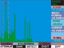
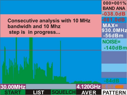
| Work in entire frequency range |
|
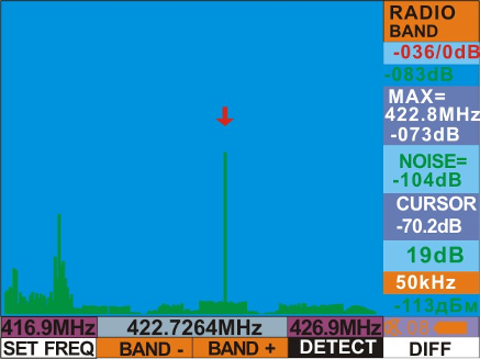
| Detailed analysis of the signals in the selected band Decrease of the swath increases signal/noise ratio in inverse proportion to the band in addition to increase horizontal resolution |
 |
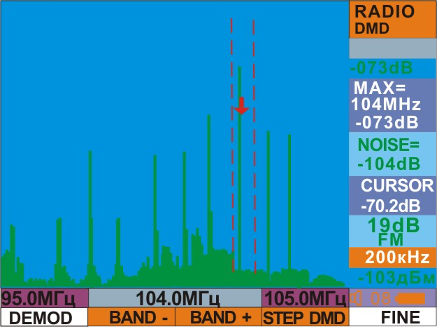
| Аudio control of the demodulated signal. |
 |
| Multi-segment scale level of signal |
 |
| Automatic detection of signals exseeds predetermined threshold with creation of database |
 |
| Instant and detailed patterns Detailed pattern automaticaly adapted for any range |
 |
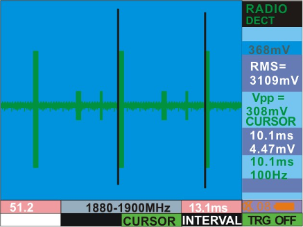
| Analysis of signals in the frequency and time domain Absolute and relative measurements using cursor lines |
 |
| Creating a list of signals in automatic and manual mode Transfer data to PC |
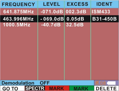 |
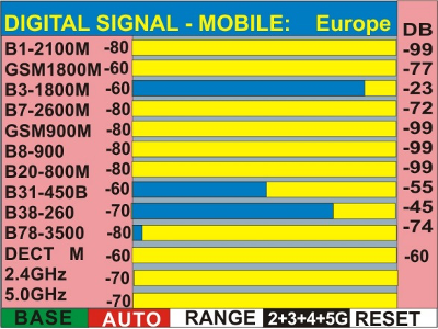
| Special indicator levels of signals cellurar and wireless data transmission Level meter of signal of base station |
 |
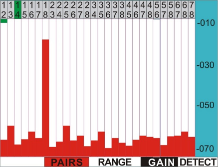
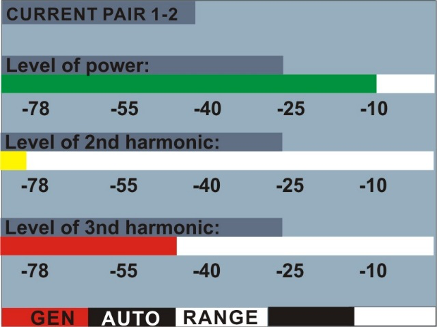
| Automatic and manual analysis of pairs of ETHERNET cable |
 |
| NON-LINEAR JUNCTION DETECTOR OPTION (only for ST131N) |
|
| FIRMWARE UPDATE Updates take place automatically when you select the latest version of the software at manufacturer's website and start the upgrade. |
 |
| MAIN UNIT | |
| DIGITAL SIGNAL PROCESSING MODULE | |
| Simultaneous processing frequency range, MHz | 0.01-30 |
| Resolution of ADC, bits | 10, 14 and 16 |
| Number of FFT points |
32768 (with PC software) 512 (the ST131 main unit) |
| DDC filter bandwidth, MHz | 0.0005-10 MHz |
| Demodulators | АМ, FM, SSB |
| Detectors | RMS, average, peak-hold, quasi-peak |
| “CH1” input | |
| Frequency range, KHz | 0.01-125 |
|
Displayed noise level - FULL RANGE, dBm |
- Minus 110 (minus 140 for PC software) |
| “CH2” input | |
| Frequency range, MHz | 0.01-30 |
|
Displayed noise level - FULL RANGE, dBm - 1 KHz bandwidth, dBm |
- Minus 110 (minus 130 for PC software) - Minus 150 |
| “CH3” input | |
| Frequency range, MHz | 30-6000 |
|
Displayed noise level dBm - FULL RANGE, dBm - 1 KHz bandwidth, dBm |
- Minus 90 (minus 100 for PC software) - Minus 110 |
| Analysis speed, not less, GHz/sec | 10 |
| Input attenuation value, dB | 0 - 30 with step 5 |
| Frequency of test signal NON-LINEAR JUNCTION DETECTOR, KHz | 150-220 |
| Indication | 3.5’’, 240x320, 262144 colors |
| Interface | USB 2.0 |
| Supply current, A | 0.4-0.6 |
| Power supply | 4 type 16650 batteries |
| Dimensions, mm | 190x97x50 |
| ST131.S.AWL | |
| Frequency range 1, KHz | 0.3-15 |
| Displayed noise range, not worse, dBm |
Minus 115 (minus 140 for PC software) |
| Input signal maximum level, dBm | 20 |
| Input amplifier gain, dB | 14, 26, 38, 44, 50, AGC |
| Common mode rejection ratio (CMRR), not less, dB | 60 |
| Maximum allowed input voltage, V | 250 |
| Frequency range 2, MHz | 0.01 - 30 |
|
Displayed noise level - FULL RANGE, dBm - 1 KHz bandwidth, dBm |
- Minus 90 (minus 120 for PC software) - Minus 125 |
| Input signal maximum level, dBm | 10 |
| Maximum allowed input voltage, V | 250 |
| Values of bandwidth, MHz |
10, 5, 2, 1, 0.5. 0.2, 0.1, 0.05, 0.02, 0.01, 0.005, 0.002, 0.001, 0.0005 |
| Input amplifier gain, dB | Plus 5, minus 1, 7, 13, 19, 25, 31, 37, AGC |
| Power supply of offset voltage | MN21x2 12V battery |
| Offset voltage setting range, V | +/- 0.3-23V |
| Frequency of test signal non-linear junction detector, kHz | 150-220 |
| Dimensions (without cable), mm | 113X62X29 |
| Length of cable, m | 0.2 |
| ST131.S.RAWL | |
| Frequency range, MHz | 30 - 4000 |
| Insertion loss, dB | 1(500MHz), 5(4000MHz) |
| Maximum allowed input voltage, V | 250 |
| Dimension, mm | L=64, D=22 |
| ST131.S.MF | |
| Frequency range (for passband ripple 4dB), Hz | 30-30000 |
| Threshold sensitivity, at 1000 Hz, not worse, A/m*Hz1/2 | 2*10-6 |
| Dimension, (without cable), mm | |
| ST131.S.SHF | |
| Frequency range, MHz | 6000 - 18000 |
| Directional pattern width, degree | 60-90 |
| Dimensions (without cable), mm | 235X45X22 |
| ST131.S.IR | |
| Frequency range, nanometers | 220-3200 |
| Measuring range (1MHz), dB | -40/+10 |
| Subcarrier frequency range, MHz | 0.01-5 |
| Spectral range, nm | 770 – 1600 (550-1100) |
| Field of view, degree | 10 |
| Dimension, (without cable), mm | L=55, D=26 |
| Basic set | |
| 1 Main unit | |
| 2 Power supply | |
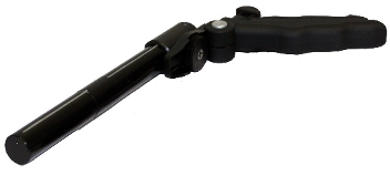
| 3 Main unit’s supporting device | |
| 4 Main unit’s shoulder holder. | |
| 5 USB cable | |
| 6 Li-pol akk. type 16650 (4 pcs) | |
| 7 USB flash drive with software | |
| 8 Technical description and operating manual | |
| Additional set | |
| 1 “ST131.S.AWL” – wire line adapter+”RJ-45” cable +220V clips (2 units)+ "GROUND" wire+ Probes set + alligator clips+ battery12V MN21(2ps.) | |
| 2 “ST131.S.SHF” - SHF antenna-detector | |
| 3 “ST131.S.IR” - infrared sensor | |
| 4 “ST131.S.TEST” - testing device | |
| 5 “ST131.S.MF” - Magnetic field sensor | |
| 6 “ST131.S.UHF.A” - broadband UHF antenna | |
| 7 Telescopic antenna | |
| 8 «ST131.RAWL» - RF wire line adapter+«F-BNC» | |
| 9 “ST131.S.A” Acoustic sensor | |
| 10 Tripod | |
| 11 Headphones | |