ST 034


The ST 034 Multifunctional Detection device is used to detect and locate various appliances used for furtive acquisition of information (hereinafter called ‘Special Technical Means’, or ‘STM’), to reveal natural and artificial channels of information leakage.
The STM with transfer of information by radio channel. Such devices include first of all:
- Radio microphones.
- Telephone radio broadcasting devices.
- Radio stethoscopes.
- Wireless Video cameras.
- Mobile telephones and modems of CDMA, GSM, UMTS, DECT standards used without authorization
- The devices using digital channels of data transmission of WLAN and BLUETOOTH standards.
- Radio beacons for object movement tracking.
The STM that use AC power, telephone, security and fire alarm lines for information transfer.
The STM characterized by information transmission in infrared range.
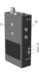
MAIN UNIT
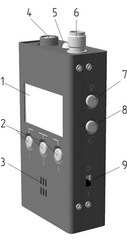  |
1 |
Graphic display |
|
2 |
Control buttons | |
|
3 |
Grid of the in-built speaker | |
|
4 |
Socket for external probes | |
|
5 |
IR probe | |
|
6 |
TNC connector | |
|
7 |
Button backlight | |
|
8 |
Button of MENU and ENTER | |
|
9 |
Switch power ON/OFF | |
|
10 |
Buttons «+» и «-» | |
|
11 |
Headphone socket | |
| 12 | USB socket | |
| 13 | Charge indicator |
ADAPTER OF WIRE LINES (AWL)
In the AWL two transformers are united:
AWL saves serviceability at presence on input connectors of voltage (AC or DC) no more 250V.
 |
1 |
Fine-tuning the level of common mode |
|
2 |
Switch ON/OFF 20dB attenuator | |
|
3 |
Choice of MODE | |
|
4 |
Indicators of voltage in wire line | |
|
5 |
Input connectors |
ADDITIONAL CONVERTORS
SHF DETECTOR «ST 03.SHF»
MAGNETIC FIELD PROBE «ST 03.MA»
DETECTION CHANNELS
ST 034 has seven detection channels:
- UHF detector - frequency meter
- SHF detector
- Wire line analyser
- IR detector
- Differencial amplifier
- Magnetic field detector
- Acoustic probe
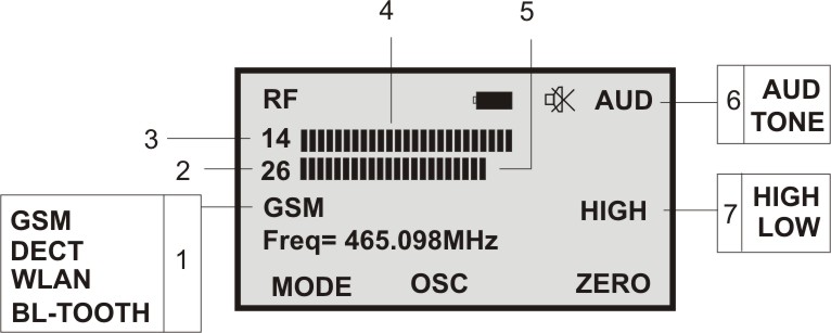
UHF DETECTOR /FREQUENCY METER CHANNEL
The operation principle of this channel is based on a broadband detection of electromagnetic power. Signal magnitudes are displayed on two 32-segment scales.
The difference between the two scales is as follows: the upper scale indicates the amplitude mean of the average detected signal, whereas the lower one indicates its peak values. Therefore, in the upper scale, AM- and FM-modulated signals will predominate, whereas the lower scale will be registering pulse-, or pulse-like, signals (e.g. DECT, GSM) If indication takes place in both scales, this means that a mixed type signal (such as TV signal) is being received.
In this mode, current values of the incoming frequency are measured (signals with a constant carrier frequency).
The device will advise you if the detection of a GSM, DECT, WLAN or BLUETOOTH signal takes place.
|
|
1 |
Identified data transfer standards (GSM, DECT, DECT BASE, BLUETOOTH or WLAN) |
|
2 |
Current value of impulse component level, comparing with zero level, dB | |
|
3 |
Current value of constant component level, comparing with zero level, dB | |
|
4 |
32-segment scale, indicating the integral power of the radio source |
|
|
5 |
32-segment scale, indicating the pulse magnitude of the radio source |
|
|
6 |
Variants of sound control | |
|
7 |
Sensitivity of scale | |
|
8 |
Frequency of stable sygnal |
SHF DETECTOR CHANNEL
Principle of operation of this channel is based on broad band detection of electrical field in frequency range 2.5 - 10GHz using ST03.SHF.
WIRE LINE ANALYZER CHANNEL
The receiving part of the channel represents the double superheterodyne with a PLL frequency synthesizer
Reception of signals is carried out by automatic or manual scanning in frequency range from 0.015 to 15 МHz.
At a scanning stop acoustical control of the signal, with choice АМ or FM demodulator is provided.
ST 034 connects to the line under investigation via AWL.
 |
1 |
Current tuning frequency |
|
2 |
Type of demodulation | |
|
3 |
Differencial Mode | |
|
4 |
Indication of Mode and scanning directions | |
|
5 |
Treshold of the stop of scanning | |
|
6 |
Level of signal |
INFRARED CHANNEL
In this channel infrared radiation reception on the built in photodiode is provided.
 |
1 |
Frequency of the maximum garmonic in current signal. |
|
2 |
Numerical value of level of signal | |
|
3 |
Scale of level of signal |
Additional indication with use of octave filters is provided
 |
1 |
Six scales of level of a signal with value of central frequency 0.25, 0.5, 1, 2, 4 и 8 kHz |
|
2 |
Mode indication «FAST» and «SLOW» | |
|
3 |
Numerical value of level of signal |
DIFFERNTIAL AMPLIFIER
In this mode, the device is set to receive signals in conductive lines.
The detection of microphones, both active, and passive (not equipped with a preamplifier) is posible.
Magnitude and frequency indication is available, as well as sound for audio monitoring.
ADDITIONAL POSSIBILITIES
OSCILLOSCOPE
 |
1 |
Oscillogram |
|
2 |
Horizontal range | |
|
3 |
Vertical range (AUTO - autoselect vertical range) |
SPECTRUM ANALYZER
 |
1 |
Spectrogram |
|
2 |
Horizontal range | |
|
3 |
Vertical range (AUTO - autoselect vertical range) |
|
SPECIFICATIONS
|
|
| UHF detector - frequency meter | |
| Frequency range, MHz |
20-3000
|
| Sensitivity at input, dBm |
< minus 50 (20 MHz - 2000 МHz)
< minus 40 (2000 МHz - 3000 МHz) |
| Dynamic range of indication, dB |
50
|
| Sensitivity of frequency meter, dBm |
< minus 30 (100 МHz - 2000 МHz)
< minus 25 (2000 MHz - 2500 МHz) |
| Frequency measurements accuracy, MHz |
±0.1
|
| Identification of protocols |
GSM, DECT, WLAN, BLUETOOTH
|
| SHF detector | |
| Frequency range, GHz |
2.5-10
|
| Threshold sensitivity, W/cm² |
2.5*10-10
|
| Dynamic range, dB |
32
|
| Type of antenna |
log-periodic
|
| Polarization |
Horizontal
|
| Antenna beamwidth, degrees |
60-90
|
| Wire line Anylaser | |
| Frequency range, MHz |
0,05-15
|
| Sensitivity, at s/n 10 dB, dBμV |
<35
|
| Filter bandwith, kHz |
20
|
| Demodulation types |
AM, FM
|
| Maximum allowable input voltage, V |
250
|
| Differential Amplifier | |
| Frequency range, kHz |
0.3-12
|
| Common-mode rejection ratio (CMRR), dB |
>60
|
| Input impedance, kOm |
75
|
| Input Voltage Noise, μV |
<2
|
| Dynamic Range, dB |
50
|
| Maximum allowable input voltage, V |
250
|
| Magnetic Field detector | |
| Frequency range, kHz |
0,4-12
|
| Threshold sensitivity, Т/Hz1/2 |
10-11
|
| Dynamic Range, dB |
50
|
| Acoustic analyzer | |
| Frequency range, kHz |
0.3-8
|
| Dynamic Range, dB |
50
|
| IR detector | |
| Spectral range, nm |
750-1100
|
| Frequency range, kHz |
0.3-300
|
| Threshold sensitivity, W/Hz1/2 |
≤10-13
|
| Angle of sight, degrees |
30
|
| Power | |
| Power supply |
Li -pol acc. 3.7V
|
| Maximum consumed current, mA |
<100
|
| PC transfer interface |
USB
|
| Dimensions, mm | |
| Main Unit |
125x62x28
|
| Package |
250x160x140
|
| Weight, kg | |
| Main Unit |
0.25
|
| Complete set | |
| Main Unit | 1 |
| Universal adapter of wire line | 1 |
| Telescopic antenna | 1 |
| UHF antenna | 1 |
| Test Leads | 1 |
| Cable USB | 1 |
| Power Supply unit | 1 |
| Mini Cd | 1 |
| User Manual | 1 |
| Packaging Bag | 1 |
|
Additional complete set |
|
| SHF antenna detector ST03.SHF | 1 |
| Magnetic field probe ST034.MF | 1 |
| Acoustic probe ST034.A | 1 |