ST 158

This task is achieved through the installation of the control module (hereinafter CM) inside the coverage area of the jamming device. There is a condition like one CM per one jamming device.
- During the installation of the cell phone jamming device, it is not paid sufficient attention to checking the blocked area and matching the frequency band for jammers and a cell tower in the local place.
- Usually this is done on the basis of an examination the link between the base station and the cell phone for one or two providers. However, a check of all mobile providers is necessary. There may be more than five of them.
- Over time, a mobile provider can change the location, the number of base stations, which leads to a change in the signal strength and (or) the frequency band at the installation location of the jamming device.
- The jammer is a sophisticated radio transmitter and it can break down while working. Fast detection that breakage is difficult.
OVERALL POSITION
The cell phones using CDMA 450, GSM, 3G and 4G mobile technology standards are separated in frequency receive and transmit paths. A jammer is an instrument used to prevent cell phones from receiving signals from base stations. To reliably suppress communication between the base station and the mobile device the jamming signal level must exceed the level of the received base station signal by a certain value ("suppression factor").
So, to estimate the effectiveness of the jammer, it is necessary to measure the signal strength of base stations of all providers in the monitored area as well as the signal strength of the jammer in the all frequency bands which are supposed to be suppressed.
DESCRIPTION OF THE СM
The СM is composed of:
- radio-receiving unit working in frequency bands according to mobile standards
- transceiver for providing communication via WLAN or ETHERNET networks (in version of data transmission into the checkpoint PC)

|

|

|
| ST158E/ST158E+POE | ST158.W |
ST58.A |
The checkpoint PC is considered as a desktop PC, laptop or Windows-compatible tablet with installed special software.
The surface of the СM has:
- Connector for power supply
- Power switch
- SMA connectors for connecting RF antennas.
- LED Alarm and status of CM.
- USB connector.
- RJ-45 connector (only for ST158 E or ST158E+POE)
- WLAN antenna (only for ST158W)
Parameters of light and sound alarm are set via the USB port.
A wide range of frequencies and adapted firmware allow you to quickly reconfigure for any frequency bands of local mobile providers by using ability to update the firmware via the Internet.
OPTIONS OF CONFIGURATION OF THE SYSTEM
|
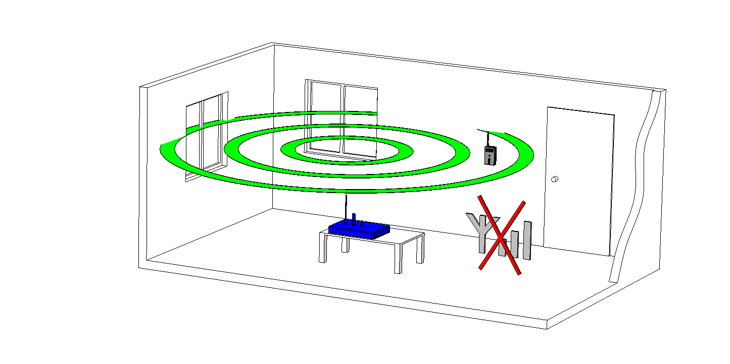
Light and audible alarm indication (ST158A).
This option is designed for monitoring one or two jammers in one room by using ST158A |
|
|
Alarm transmission into the PC using existing or specially created WLAN (ST158W) or ETHERNET network (ST158E or ST158E+POE).
|
|

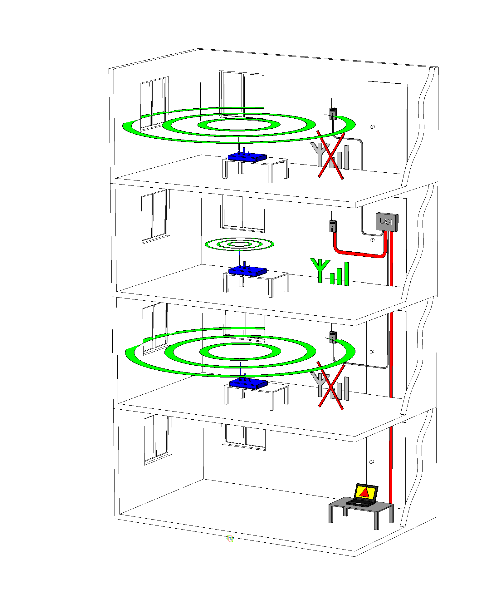
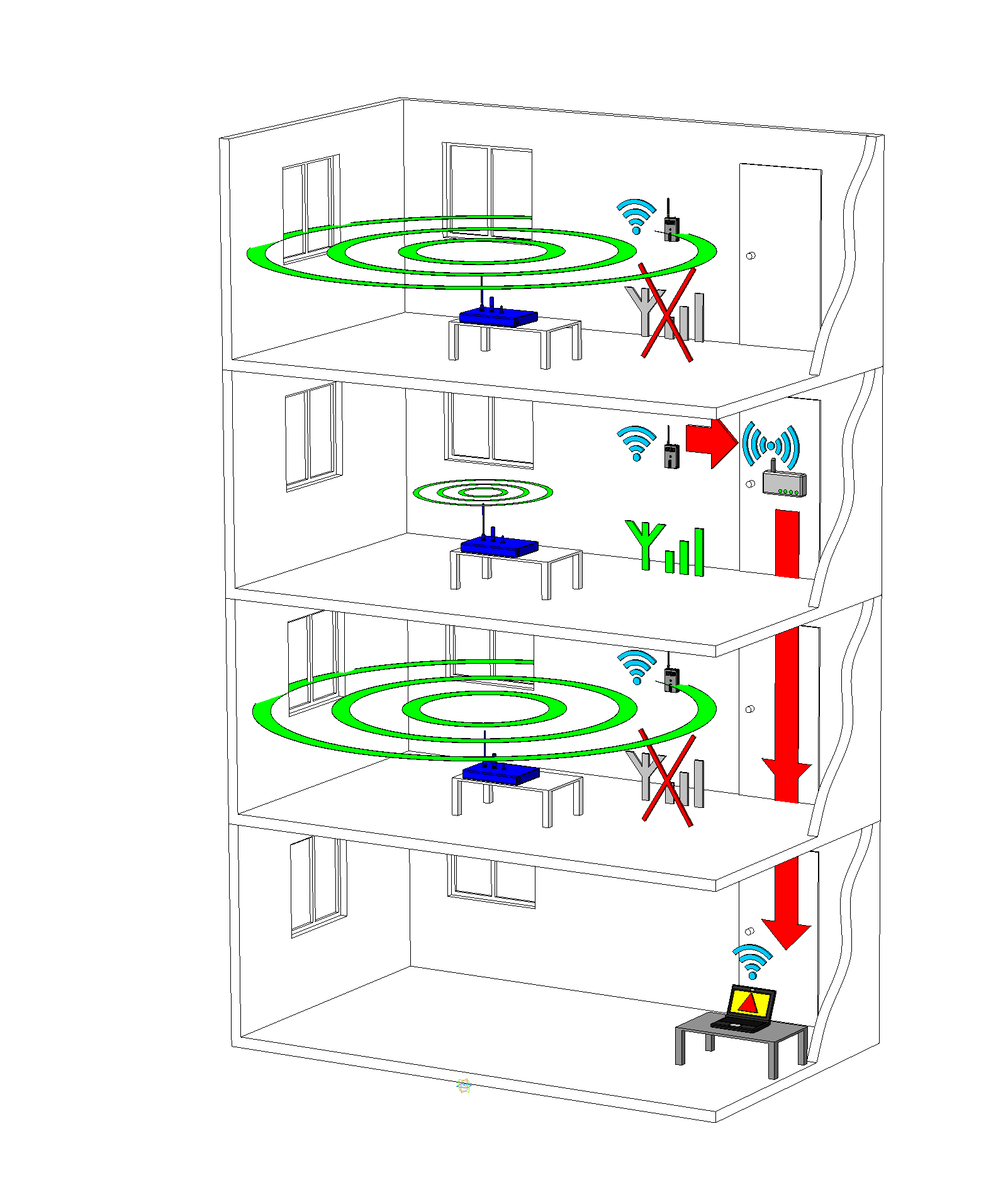
This option is designed for monitoring many jammers in a multi-storey building as well as in one room.

ALGORITHM OF WORK WITH THE SYSTEM
|
The first step
Press the button "Grab Base Station Levels". Spectrum level of all base stations at the installation location will be measured and recorded into the memory. The screen displays a red line above this level by a factor of suppression. The value of suppression quality will be 0%. |

|
|
The second step
Turn on the jammer. The jamming spectrum must appear on the screen. The value of suppression quality near the jammer should be 100%. |

|
The third step.
Check the real jamming area by moving the CM and watching the displayed value of suppression quality for the selected value of suppression factor.
Installation.
The CM is set up at the border of the monitored area.
Press the "Save Pattern" button. The jamming spectrum will be memorized into the CM.
The work.
|
The CM will give an alarm signal if the jamming signal strength is reduced or the jamming spectrum is changed. Also, there is a procedure to inform when the signal strength of base stations has been changed because that affects on the size of the blocked area. |

|
| SPECIFICATIONS | |
| Full frequency range | 25-6000 MHz |
|
Maximum input level, dBm |
-5 |
|
Interfaces |
USB, WLAN, ETHERNET |
| Supply voltage, V | 5 |
|
Consumption current, mA, not more than |
500 |
|
Dimensions without antenna, mm |
109x60x27 |
| Delivery set | |
| ST 158 | 1-128 |
| Bag | 1 |
| User Manual | 1 |